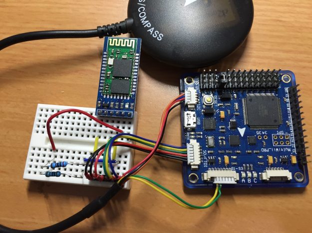
I started by connecting the HobbyKing AIO board to the GPS that I bought from HobbyKing for $35 and to the HC-05 Bluetooth module. This allows me to configure the AIO via BT.
The connections are as follows:
GPS to AIO board
The UBlox Neo-7M GPS comes with a cable that has 2 mini-molex connectors, one with 4 pins and one with 5 pins.
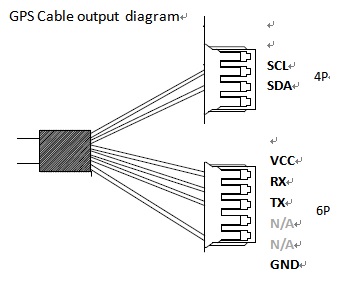
Some changes must be made to these connections in order to fit them to the AIO board. Moving the cables between pins is simple – lift the flap that holds the cable inside the connector and pull the cable out. See the photo below.

The changes to cabling are as follows:
4-pin connector
The 4 pin connector is connected to the i2C connector on the AIO.
It should have the following cable connected to it, from top (leftmost) to bottom:
- SCL – moved from pin 2
- SDA – moved from pin 3
- VCC – moved from the 5-pin connector
- GND – moved from the 5-pin connector
5-pin connector
The TX and RX cables from the 5-pin connector must be connected to RX2 and TX2 on the AIO board respectively. So I replaced the 5-pin connector with a 6-pin connector that I had from the AIO package and connected the TX and RX cables at the right slots.
AIO board to HC-05 BT module
The BT module connects to the FTDI port on the AIO as follows:
- AIO GND —> HC-05 GND
- AIO VCC —> HC-05 5V
- AIO – RX —> HC-05 TX
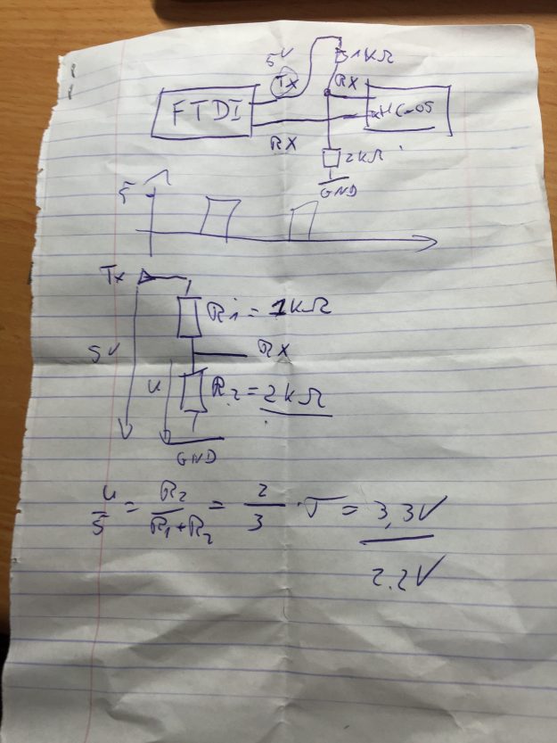
- AIO TX is connected to HC-05 RC via a voltage divider in order to protect the HC-05. The HC-05 uses 3.3V while the output of the AIO board may be 5V. The following photo of a crumpled piece of paper shows the two resistors that form the voltage divider.
AIO external power
The AIO receives 5V power from an external source on the GND and VCC pins.
